Use Case Diagrams
DISCLAIMER: I am not a big fan of Use Case Diagrams. And because I don't use them much, it is entirely possible that there are mistakes in this wiki article. I have done my best to make it accurate though, and my sources are documented at the bottom. If you wonder what I suggest as an alternative, please see my blog post: Do We Really Need Use Case Diagrams?
What is it?
Originally developed by Ivar Jacobson when he was still at Erickson, a Use Case Diagram is a visual model that depicts key system functions accessed by those outside the system and the actors that interact with those functions. It is one of the most-widely use UML models and most business analysts should be familiar enough with them to at least use them casually.
Use Case Components
Use Case Diagrams are made up of five standard components. They are:
The system being modeled. The system is generally represented as simple rectangle into which the use cases are placed. The system name is commonly added just inside the top border of the rectangle.
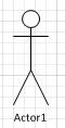
The actors who interact with the functions of the system being modeled. Actors are always placed outside the system boundary and represent general roles, not specific individuals. For example, an Actor would be “Student”, but not “Bill Jones”, and probably not even “12th Grade Student”. Actors can also be other systems that interact with the system being modeled. Human actors are generally represented by stick figures while system actors are generally represented by rectangles with the other system name enclosed in double triangle brackets (i.e. <<system name>>. An example of human actor is below:
The use cases of the system. These are high-level functions that will be further documented in the form of the textual use cases, not diagrams. They are what an Actor would like the system to do; and are usually named in the form of a present tense verb+object pair, such as “Update Inventory”, “Hire Employee”, “Order Food”, and similar names. Use cases are represented in the diagram by ellipse like this:

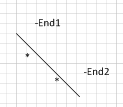
The associations between actors and use cases. Sometimes also referred to as Connections. These associations indicate that the use case will be initiated by the actor(s), or that they participate in the Use Case or benefit from it. There seem to be two different standards for how Associations are represented. In some cases it is by a simple line (not an arrow) between the actor and any use cases they directly interact with; and in other cases it is a solid line arrow leading from the initiating actor to the use case or from the use case to any participating or benefiting actors. An example of the simple line option is below:
The relationships between different use cases. There are two different types of relationships, the Extend relationship and the Include relationship.
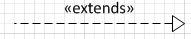
- An Extend Relationship indicates that the functionality of one use case is extended by adding new behaviors or actions, resulting in an expanded version of the original use case. For example, a normal “purchase item” use case might be extended with additional functionality enable a user to purchase an item that is not in stock, to be a “purchase out of stock item”. The “purchase item” use case has additional functions added that are needed if the desired item is out of stock, but for most part remains the same. Extend Relationships are indicated in the diagram by a dotted-line arrow that points from the extension use case pointing at the use that was extended, with the label “<<extend>>” added on the arrow. Like the example below:
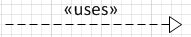
- The other type of relationship is the Include Relationship, which indicates that one use case completely includes the behaviors and actions of another use case. This is frequently done when the Included use case describes a generic feature that would be needed in several other use cases. For example, the
purchase item
use case above might Include aupdate inventory
use case that is also included byreceive inventory
use case. Include relationships are indicated by a dotted-line arrow pointing from the use case that includes the generic use case, to the use case that is being included, with the label “<<include>>” added to the arrow. Note that in Visio an Include relationship is called aUses
relationship. Like the example below:
- A key point about relationships is that
Include
(orUses
) relationships are mandatory and always uses when theparent
use case is called, whileExtend
relationships are optional and may not be called every time theparent
is called.[2]
Characteristics
Use Case Diagrams have several characteristics that separate them from other diagrams and models used in requirements work.[3]
- Use Case Diagrams are a
wide
view of a system, but not a deep one. The use cases contained in the diagram are very high-level functions such asTake Photograph
, instead of deep ones such asOpen Shutter
,Fire Flash
, orClose Shutter
. - Use Case Diagrams only model functional capabilities. They do not model non-functional capabilities such as business rules, constraints, quality of service specifications, or similar capability needs.
- Use Case Diagrams do not show sequence, order, or flow. Unlike sequence, activity or flow diagrams.
- Use Case Diagrams do not model data in any way. Rather than describing data, they describe the things that can be done by the system that contains or uses the data.
- Unlike descriptive Use Case (aka Use Case narratives, Use Cases, Use Case Descriptions, etc.), Use Case Diagrams do not include any Exception behavior.
- The use cases in the diagrams are a black-box and do not specify how the functionality will be implemented. They just specify the needed functionality at a very high level.
Mis-Use Cases
You can use the exact same format of Use Case Diagrams to instead make Abuse Case
or MisUse Case
diagrams.
Rather than diagramming functions that actors want the system to do, you instead diagram use cases that are things you don’t want someone to do. See Reference item 6 for the basic concept, while Reference item 7 significantly expands on the idea.[6. 7]
Why do it?
Use Case Diagrams describe the relationships between requirements, users, and the major components of a system. It does not describe the requirements in detail. Thus, they are high-level requirements artifacts.
Use Case Diagrams are created to help identify:
- Questions of scope (what functionality is potentially in or out of scope),
- Stakeholders (the actors who interact with the system),
- Major functional needs of the system to be developed
Use Case Diagrams are frequently among the earliest models or diagrams created during the enterprise analysis or requirements elicitation work.
These initial Use Case Diagrams are then elaborated, supplemented, and expanded through (descriptive) Use Cases (non-diagram Use Cases), additional models and diagrams (such as UML Activity, Sequence, and Class Diagrams), or in other more-detailed requirements artifacts (detailed functional and non-functional requirements) as more information is learned and as more detailed requirements are defined.
How do I do it?
Step 1
Decide which system you are going to model. This may be a full system, or a component of a larger system.
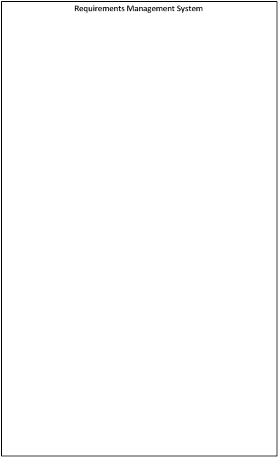
ExampleAs an example, I am going to walk through the process of creating a Use Case Diagram for a simplified (but not too simple) Requirements Management System.
I am going to use Visio for this, so that may limit my options for the diagram.
Step 2
After I place the system boundary to start the diagram, it looks like this:
Example
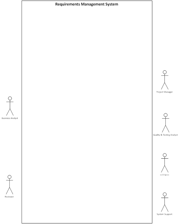
Step 3
Define the actors. One way to identify actors is that they are things that cannot be controlled by the system yet which interact with it. This helps to identify both human and non-human (other system) actors.
Example
For my Requirements Management System, I identify the following actors:
- Business Analyst – To work with various requirements artifacts
- Project Manager – To work with project functionality
- Reviewers – To review and provide feedback on the project artifacts
- Quality & Testing Analysts – To provide feedback on artifacts and write test cases
- System Support staff – To manage the application
- Team Foundation Server (TFS) – The only non-human actor, used by the development teams, data is passed back and forth between the systems.
As a result of defining those actors and adding them to my diagram, it now looks like this:
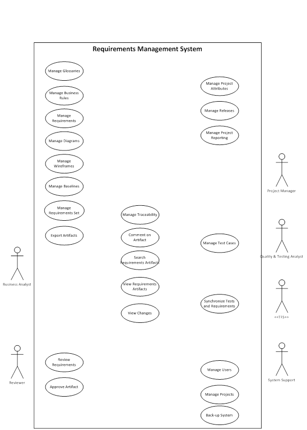
Step 4
Start adding the use cases. As a guide, any functionality that is not interacted with by an actor should not be included in the Use Cases that are part of the diagram. Also, the use case should be of sufficiently high-level that is should make sense for an actor to do ONLY that thing during a session.[3] To use the photograph metaphor above, it makes sense for a user to Take Photograph
and do nothing else. It does not make sense for a user to Open Shutter
and do nothing else.
A good place to start with defining use cases is with any goals you have specified that your system should meet. Depending on the level of detail you have defined your goals at, the goals may be use cases in themselves, or can be decomposed into functionality (use cases) needed to meet the goal.
After the goals, you should also engage with representatives of your actor types (your SME’s and/or stakeholders) and ask them for list of things they would expect to be able to do with the system you are defining.
Example
So I go to each actor and ask them what they would want the new system to do, and get the following results.
Business Analyst
- Work with Glossaries
- Work with Business Rules
- Work with Requirements
- Work with Diagrams
- Work with Wireframes
- Define Requirements Sets
- Baseline Requirements
- Do Traceability
- Search for Requirements
- See Changes
- Comment on Requirements
- Export Requirements
Project Manager
- Specify requirements for releases
- See Project Reporting
- Define Project Attributes
- View Requirements
- See Changes
- Comment on Requirements
- Search for Requirements
- See Trace Relationships
Reviewer
- View Requirements
- Search for Requirements
- Comment on Requirements
- See Changes
- See Trace Relationships
- Approve Requirements
Quality & Testing Analyst
- View Requirements
- Search for Requirements
- Comment on Requirements
- See Changes
- See Trace Relationships
- Define Tests
System Support
- Control Access
- Set up Projects
- Back-up the System
So after that gathering the information above, one thing to notice is that many of the verbs are very specific (such as Define
) and that the user may actually want more functionality than that. So I often use the verb Manage
instead, and clarify with the project team that Manage
includes verbs like create, edit, and delete.
With some changes to the verbs and objects, I add the Use Cases to my diagram so that it looks like the one below:
Step 5
Add the connections. Generally, the only connections that should be included in your model are connections between actors and use cases. You should not employ a use case diagram to show interactions between actors as the use case diagram is system focused.
Example
Using my list of who wanted what, I add the connections and get the diagram below:
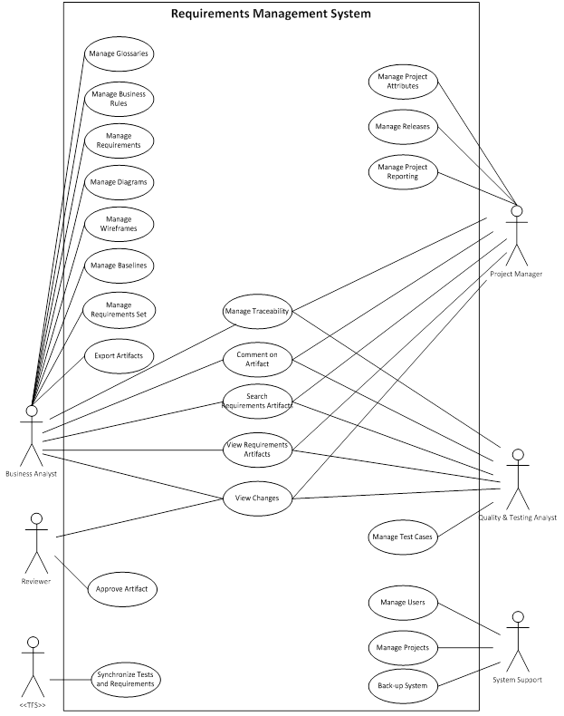
Step 6
Refine any use cases by adding Relationships.
Example
Looking at the last version, the diagram is bit busy, but not too overwhelming. However, now it’s time to start thinking about Relationships. So I make the following changes:
- I notice that everyone wants to view changes and I also think this would be a great universal functionality.
- I could make a “Version Artifacts” use case and make it an Includes/Uses for all of the “Manage” use cases, but remember that a Use Case is supposed to be something an actor interacts with.
- So instead I will define a “Manage Artifact Versions” use case that encompasses not just automatic versioning, but also that ability to go in and manage those versions. This then becomes an Includes/Uses use case.
- I also notice that there are a number of use cases that really seem to be functions that build on “Viewing Requirements Artifacts”. These include things like viewing changes, adding comments, and managing traceability relationships for that requirement. So all of those add Include/Uses relationships with the View Requirements use case.
- I consider that when exporting requirements artifacts, I will be exporting a specific set of requirements, so I make Exporting an Extension of Managing Requirements Sets.
- Lastly, I notice that I have managing baselines and requirements sets as two separate use cases. But a baseline is just a specific set of requirements, so Managing Baselines should be an Extension of Managing Requirements Sets.
When all of those changes are made, the result is a diagram like the one below:
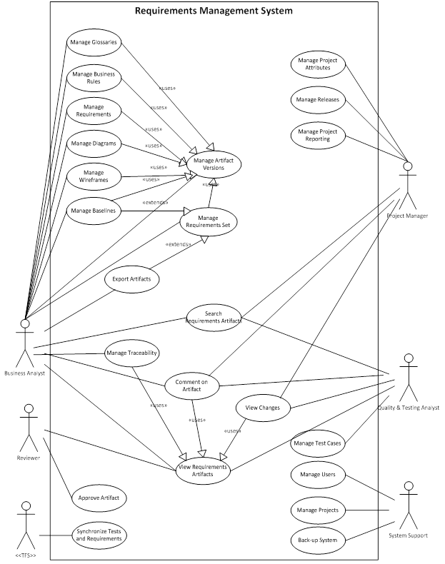
Step 7
Review, validate, and further elaborate.
Example
I this example, I believe I have captured the various use cases, so I just try to clean up the diagram slightly to make it more understandable. I could try and break up the diagram into separate smaller diagrams that are more focused on specific functional areas (requirements creation and management, project management, system management, reviews and approvals, etc.), but that violates the general goal of modeling a system (rather than just parts of them).
So the results final look like this:

What Should the Results be?
The final diagram should look something like the one in Step 7 above. Hopefully, your system is much simpler or you are much better than I am at creating Use Case Diagrams.
Validation Rules
In general, your Use Case Diagrams should comply with the following rules in order to be “valid”:
- Each Actor should be Associated with at least one Use Case.
- Each Use Case should be Associated with at least one Actor.
- Actors should not be Associated to other Actors.
- Use Cases should not be Associated with other Use Cases (they may have Relationships).
Advantages
- Use Case Diagrams are usually easy for anyone to understand with a minimal amount of explanation.
- Use Case Diagrams are extremely useful in the early phases of a system development effort and lay an excellent foundation for the further definition of requirements into multiple formats in greater levels of detail.
Disadvantages
- It is very easy to create too many use cases by trying to define a higher-level of detail.
- Because Use Case Diagrams focus purely on function capabilities, it is easy for those involved in their creation or who read them to overlook critical non-functional requirements.
Tips
- Scott Ambler provides the idea of using multiple system boundary boxes to denote which functionality will be included in each release when using phased or iterative delivery.[5]
- For improved readability of the diagram, it is often a good idea to place use cases one above the other. But this is not required.
References
- Book: Modern System Analysis and Design, Fifth Edition - Chapter 7 Appendix: Object-Oriented Analysis and Design. By Hoffer, George, and Valacich. Pearson Prentice Hall. 2008.
- Book: Business Analysis Techniques - 72 Essential Tools for Success. By Cadle, Paul, and Turner. BCS. 2010
- Article: UML Use Case Diagrams - Tips and FAQ. By Rus Heywood. From the 1999 Carnegie Mellon University Object-Oriented Analysis and Design course.
- Article: UML Use Case Diagrams – Reference. By Microsoft.
- Article: Use Case Diagrams. By Scott Ambler. AgileModeling.com.
- Research Paper: Using Abuse Case Models for Security Requirements Analysis. By John McDermott and Chris Fox. Computer Security Applications. 1999.
- Research Paper: Eliciting Security Requirements with MisUse Cases. By Guttorm Sindre and Andreas L. Opdahl. Requirements Engineering. 2005.
Related Resources
- Blog: The Use Case Blog. By Case Complete.
- Article: UML Use Case Diagram. Author not specified. On the Tutorialspoint web site.